Multi-Agent Robotics Research Lab (ROS, Aruco, Controls, Regression)
This page is currently under construction!
Introduction
I joined Professor Jorge Cortes in his research in multi-agent robotics as an undergraduate while they were in the process of moving away from turtlebots for their multi-agent algorithms.
We began prototyping and experimenting with other robot architectures. The first of which is a simple three-wheeled omnidirectional robot. This new design is an improvement to the turtebot’s limited movement capabilities. This is achieved through mounting the omni-wheels/motors at 120 degree angles of each other, and linear combinations of motor forces allow the robot to move in any direction.
Results
Using the transform of the detected Aruco cube to calculate the pose of the camera, I am able to localize the robot within the frame of the marker, using it as an origin. A goal pose can be published to a ROS topic, via tablet in the video below, the robot is able to move to that position in the Aruco’s frame.
And here’s how I did it:
Kinematics and Controls
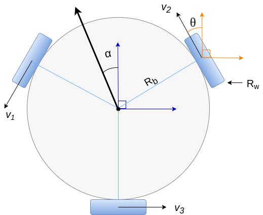
In developing the controls for this robot, I needed to convert a desired velocity vector into a rotational velocities on each wheel. Each wheel’s output makes a contribution to a vector sum which results in the desired direction of the robot in space.
Let the robots position in space be denoted by and the velocities be defined as . Starting from the translated frame of reference, denoted by the orange axes, the frame of reference for wheel 2 is offset by a positive rotation of . we can calculate the wheels contribution as a sum of the x and y components of the vector. Note that in my model, angles are calculated with respect to the positive y-axis. Leaving as an arbitrary angle - in implementation it is 30 degrees - we can calculate the translated and rotated velocity as,
Note that this equation only accounts for motion with inputs as and . In order to also account for a desired , the rotational velocity of the robot, an additional component is needed:
where is the body radius of the robot.
Now, the wheel contributions for the other 2 wheels can be calculated similarly as only the angle the frame of reference is rotated differs. For wheel 1, the angle of rotation is 180 degrees more, and wheel 3 is 90 degress less. This results in the following set of equations describing the transformation from desired velocities to desired wheel contributions :
and with geometric algebra, these equations can be mathematically simplified, and rewritten in matrix form as:
Now the relation between these velocities and the angular velocity of the wheel is:
thus the resulting and final transformation to wheel velocities are:
First Prototype
Hardware
Our first prototype was quickly constructed by mounting the parts on to a perforated hobby board.
The basic BOM included:
- 3 x Motors
- 3 x Single Layer Omni-Wheels
- 2 x Motor Drivers
- 2 x 5V Rechargable USB Power Banks
- 1 X CHIP Microcontroller
We chose to use CHIP because it was a very inexpensive way to run a linux operating system, on which we can run our software.
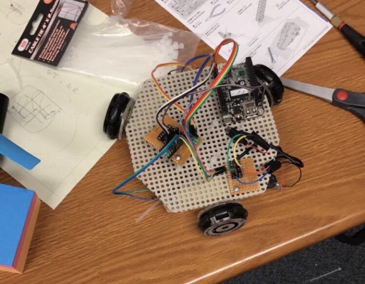 First Prototype Robot using CHIP
Software
Our software was written in the ROS framework, allowing for an easy way to interface data from sensors with our algorithms. In order to accomplish low-level movement of the robot, I wrote a ROS node using the CHIP PWM libraries that would calculate and send the necessary pwm signals to the motors based off of a published/desired duty cycle of the motor
It would be tedious to have to do position calculations in terms of individual motor speeds, rather than the system as a whole. Thus, I implemented a mid-level controller for the robot, which utilized the controls transform derived above to create an interface to bridge the low-level motor driver to any higher level software.
As seen above, this transform converts a desired velocity vector input into individual motor speeds.
Another node published the data from the camera,